|
Chamfering and gluing
up -- Stopped chamfers are routed on the legs
and aprons of this table, each terminating in a carved lamb's tongue. I
stopped routing just shy of the area to be carved and then carved the
tongue and the little shoulder in three steps (see Carving a lamb's tongue).
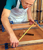
Gluing up the table base is a two-step process. First I
connected the front legs with the top and bottom drawer rails and the back
legs with the back apron. To prevent the legs from toeing in or out
because of clamping pressure, I inserted spacers between the legs at their
feet and clamped both the top and bottom. Then I check for square,
measuring diagonally from corner to corner. It ensures that the assembly
is square and that the legs are properly spaced.
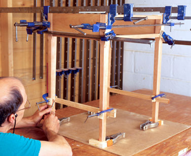
Connecting the front and rear assemblies
To hold the legs in
position while I measured for the drawer runners and kickers and, later,
to get the spacing on shelf-support rails correct, I made a simple frame
of hardboard and wooden corner blocks. The frame ensures the assembly is
square and the legs are properly spaced. After I marked the
shoulder-to-shoulder lengths for the runners and kickers, I cut and fit
the stub tenons that join these pieces to the front and rear assemblies.
The back ends of the runners and kickers must be notched to fit around the
inside corners of the legs.
 |
|
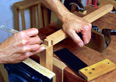
A simple frame keeps the legs
spaced accurately and the base of the table square. A 1/4-in.-thick
piece of hardboard and some scrap blocks make up this handy frame.
With the legs properly spaced, the author can mark the shoulders of
the shelf-frame rail against the tapered legs as well as take
precise measurements for runner and kicker lengths.
|
Runners, kickers and dust panel
-- I cut the 1/4-in. grooves for the dust
panel in the drawer runners next. I also cut grooves for the splines with
which I connected the drawer runners and kickers to the sides of the
table. There are 10 grooves in all--one each on the inside and outside
edges of the drawer runners, one on the outside edge of each of the
kickers and two in each side for the splines.
Then I dry-clamped
the table and made sure the tops of the kickers were flush with the top
edges of the sides, the tops of the runners flush with the top of the
drawer rail and the bottoms of the runners flush with the bottom edges of
the sides. Then I cut the dust panel to size, test-fit it and set it aside
until glue-up.
Building the shelf frame
and shelf -- The shelf on this table is a
floating panel captured by a frame made of four rails. The two rails that
run front to back are tenoned into the legs; the other two are joined to
the first pair with through-wedged tenons.
I put the dry-assembled table into the hardboard frame and
clamped the legs to the blocks. Then I clamped the pair of rails that will
be tenoned into the legs against the inside surfaces of the legs and
marked the shoulder of each tenon. I also marked the rails for orientation
so that the shoulders can be mated correctly with the legs.
Tenons
were cut and fit next. With the rails dry-clamped into the legs, I
measured for the two remaining rails to be joined to the first pair. I
laid out and cut the through-mortises in the first set of rails, chopping
halfway in from each side to prevent tearout. I cut the tenons on the
second set of rails, assembled the frame and marked the through-tenons
with a pencil line for wedge orientation. So they don't split the rails,
the wedges must be perpendicular to the grain of the mortised
rail.
I flared the sides of the through-mortises (not the tops and
bottoms) so the outside of the mortise is about 1/16 in. wider than the
inside. This taper, which goes about three-quarters of the way into the
mortise, lets the wedges splay the tenon, locking the rail into the
mortise like a dovetail.
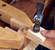
Next I marked the location of the wedge
kerfs in each tenon, scribing a line from both sides of the tenon with a
marking gauge for uniformity. I cut the kerfs at a slight angle. Wedges
must fill both the kerf and the gap in the widened mortise, so they need
to be just over 1/16 in. thick at their widest.
An interlocking tongue and groove connects the shelf to
the rails that support it. Using a 1/4-in. slot cutter in my table-mounted
router, I cut the groove in the rails, working out the fit on test pieces
first. The slots are 1/4 in. deep. I stopped the grooves in the rails 1/8
in. or so short of the mortises on the side rails and short of the tenon
shoulders on the front and back rails. I notched the shelf to fit at the
corners.
I measured the space between the rails of the shelf frame
and added 1/2 in. in each direction to get the shelf dimensions. I cut the
tongue on all four edges on the router table.
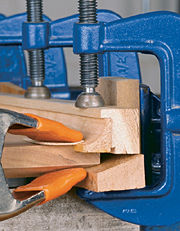
Gluing up the shelf-frame assembly -- Before gluing up the shelf frame, I routed hollows in
clamp pads to fit over the through-tenons on two of the shelf rails. Then
I began gluing up the shelf assembly. I applied glue sparingly in the
mortises and on the tenons so I wouldn't accidentally glue the shelf in
place. I pulled the joints tight with clamps and then removed the clamps
temporarily so I could insert the wedges.
After tapping the lightly
glue-coated wedges into the kerfs in the tenons, I reclamped the frame. I
checked diagonals and adjusted the clamps until the assembly was square.
Once the glue was dry, I sawed off the protruding tenons and wedges and
planed them flush.
Overall glue-up --
With the shelf frame glued up, the entire
table was ready to be assembled. I began the large front-to-back glue-up
by dry-clamping the front and back leg assemblies, sides, runners, kickers
(with splines), dust panel and shelf assembly. I made adjustments and then
glued up.
I made and fit the drawer
guides next. I glued the guides to both the sides and the runners and
screwed them to the sides with deeply countersunk brass screws.
I
did a thorough cleanup of the table in preparation for drawer fitting. I
removed remaining glue, ironed out dents and sanded the entire piece with
120-grit sandpaper on a block. I gently pared sharp corners, taking care
not to lose overall crispness.
The
drawer
I particularly enjoy making and
fitting drawers. A well-made drawer that whispers in and out gives me
great satisfaction. I use the traditional British system of drawermaking,
which produces what my teachers called a piston fit. The process is
painstaking (see FWW #73, pp. 48-51 for a description of this
method), but the results are well-worth the effort. That, however, is a
story for another day.
Making and attaching the top
After I thicknessed and cut
the top to size, I placed it face down on my bench. I set the glued-up
base upside down on the top and oriented it so it would have a 1-in.
overhang all around. I marked the positions of the outside corners and
connected them with a pencil line around the perimeter. This line is one
edge of the bevel on the underside of the top. Then I used a marking gauge
to strike a line 7/16 in. from the top surface on all four edges.
Connecting the two lines at the edges created the bevel angle. I roughed
out the bevel on the tablesaw and cleaned it up with a plane. The bevels
should appear to grow out of the tops of the legs.
Making and attaching
the coved lip -- The cove at the back of the
top is a strip set into a rabbet at the back. I cut the cove from the same
board I used for the top so that grain and color would match closely. I
ripped the cove strip on the tablesaw and handplaned it to fit the rabbet.
I shaped the strip on the router table, leaving the point at which it
intersects the top slightly proud. To provide even clamping pressure, I
used a rabbeted caul, clamping both down and in.
When the glue was
dry, I planed the back and the ends of the cove flush with the top. To
form a smooth transition between top and cove in front, I used a curved
scraper, followed by sandpaper on a block shaped to fit the cove. I
frequently checked the transition with my hand and sanded a wider swath
toward the end. It's easy to go too far and have a nasty dip in front of
the cove.
I drew the ends of the cove with a French curve and then
shaped the ends with a coping saw, chisel and sandpaper. The curve should
blend into the tabletop seamlessly.
Finishing up with oil --
After finish-sanding, I applied several coats of raw linseed oil diluted
with mineral spirits in a 50/50 mix, a few more coats of straight linseed
oil and, finally, two to three coats of tung oil to harden the surface. I
let the oil dry thoroughly between coats. After the last coat of oil was
dry, I rubbed the surface down with a Scotch-Brite pad and gave the table
a few coats of paste wax. The drawer was the exception: Aside from the
face of the drawer front, all other surfaces were finished with wax
alone.
Attaching
the top -- I screwed the top to the
top-drawer rail from beneath to fix its position at the front. That way,
the mating of the bevel with the front rail will be correct and any
seasonal movement of the top will be at the back. I attached the top to
the base with buttons on the sides and in the rear.
Stephen Lamont is a
professional furnituremaker.
Photos: Vincent Laurence; drawings:
Bob La Pointe
From Fine Woodworking #120, pp.
48-53
|