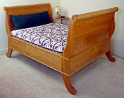
Building a Sleigh Bed
Sensuous curves and well-chosen details enhance a simple design
 | |
|
Photo: Dennis
Griggs | |
|
||||||||

I saved time on this bed by using flat panels for the headboard and footboard, rather than coopering a curved panel or using a tambour. Also, instead of carving the rosettes, I turned them (see Turning rosettes). It took less than an hour and a half.
The bed is a very simple construction. The headboard and footboard assemblies are joined to a pair of thick rails with knockdown fasteners. These assemblies are each made up of two posts into which are tenoned a turned crest rail and a flat lower rail. A single large panel floats in grooves in both posts and in the crest and lower rails.
 | |
|
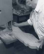
Bandsaw the post profile. Stay
outside of the line; what remains can be routed or sanded. An
outfeed table attached to the author's bandsaw makes maneuvering the
large blank much easier. | |
The crest rails had to be 61-1/2 in. long, but my lathe's capacity is only 39 in. So I farmed them out to a local millwork shop where I used to work. While I was at the shop, I ordered eight 8-ft.-long pieces of cove-and-bead molding.
I glued up the posts and rails from 8/4 stock (about 120 bd. ft., including waste) and then planed the eight planks to a bit more than 1-1/2 in. thick. I bandsawed a pattern from 3/8-in. plywood and carefully sanded the edges so that all the curves were smooth and fair. I transferred the post profile to the blanks and then bandsawed the posts, staying about 1/16 in. back from the line. I bored 3/32-in. holes through the centers of all four crest circles and all four foot circles on the drill press. These holes were essential in indexing both the pattern and the rosette and in drilling the crest-rail mortise hole. On the finished bed, the top holes were covered by the crest rail and rosettes; the holes in the feet were plugged.
 | |
|
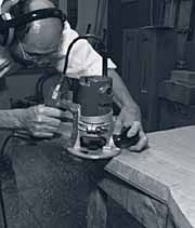
Use a flush-cutting,
bearing-guided bit and a template to rout the profile. Rout with the
grain to avoid tearout. For sections where you can't rout with the
grain, flip the post over, and reattach the template to the other
side. Rounded areas at top and bottom are smoothed on a
sander. | |
I also discovered that a 1-1/2-in. flush-cutting bit starts to burn after only a few minutes of chewing its way through 1-1/2-in.-thick cherry. After seeing this on the first leg, I changed tactics. I sanded all the convex curves I could reach, including the crest and foot circles, using a stationary disc sander and a belt sander with an 80-grit belt. For the straight portion of each post, where the side rail meets the post, I ran the post over the jointer. As a result, the router had only half as much work, and the bit burned a lot less. On tight, inside corners, where the circles meet the curves, I used chisels, gouges and files to get a neat transition. Then the real fun started. All the edges of all four posts had to be sanded to 320-grit. I used a belt sander and a block plane here and there, but for the most part, it was burned fingertips. Incidentally, the 80-grit disc sander marks were easier to sand out than the router burns.
Laying out and cutting mortises
The next step was to decide which side of each post was going to be the face. I marked the faces with a pencil and then drilled a 1/2-in.-deep, 2-in.-wide hole on the inside center of each of the crest-rail circles. These holes matched the tenons turned on the ends of the two crest rails.
|
||||||||

I routed the mortises using a fixture that has two parallel fences with pieces connecting them. The distance between the fences is the diameter of the router base. For ease of operation, I used two routers. The first, with a 5/8-in.-dia. bit, made three passes to achieve the mortise's full 1-1/4 in. depth. With the second router, I used a 3/4-in.-dia. bit to take the mortise to its full width.
When all four mortises were routed, it was time to cut the end rails to length. Because this is a queen-size bed, I allowed 60-1/2 in. between the posts. With the addition of a 1-1/4-in. tenon on either end, that brought the total rail length to 63 in.
I cut the rails to length and then cut the tenons (remember, they're offset -- a 1/2-in. shoulder on the outside and a 1/4-in. shoulder on the inside), leaving 1-1/2-in. shoulders at the top and bottom for an overall tenon width of 9 in. I rounded the ends of the tenons with a knife, so they would conform to the routed mortises in the posts. Then I dry-fitted the rails in the mortises. Be sure that the rails are flush with or slightly in from the posts. It's much easier to take a little off the back of the post than it is to sand down the whole rail.
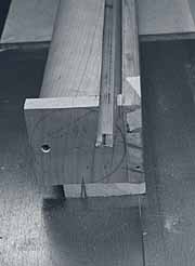
Build a box to groove the crest rail -- I needed to cut 3/4-in.-wide by 1-1/2-in.-deep grooves at 10� along the entire length of both round crest rails to accept the headboard and footboard panels. This required some creative thinking. My solution was to drill centered 1/2-in.-deep by 2-in.-dia. mortises in two 4-in.-sq. end caps and slip the caps over the tenons on the crest rail. I set the whole thing flat on the tablesaw and outfeed table and connected the end caps with two pieces of scrap -- one on the side to run against the fence and another on the top to keep the jig from racking. Screws through the end caps keep the crest rail from rotating while being cut. Remember to keep screws away from the area being grooved.
I laid out the location of the groove on the end cap, put the 3/4-in. dado set on the saw and adjusted its height and angle. I set the fence to align with the marking on the end cap and ran the entire unit through the blade. Only one end cap had to be removed to repeat the operation with the second crest rail.
With the dado in place and already tilted, I cut the identical groove in the tops of the head and foot rails. Remember that head and foot panels tilt out from the bottom rails and, unlike the crest rails, cannot be reversed. Think before you cut.
 |
 | |
|
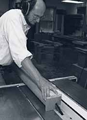
A two-sided box with end caps
holds the crest rail at a fixed angle to the blade and provides a
flat surface to run against the fence. |
Tenons on the ends of the crest
rail fit snugly in mortises in the end caps, which are screwed to
the crest rail and to the two sides of the
box. | |
Sized stick provides layout lines for head- and footboard panels -- The next trick is to lay out the grooves for the headboard and footboard panels on the inside faces of the posts. To do this, I used a stick to align the grooves that were already in the crest and lower rails. I set one of the posts face down on a pair of low sawhorses and placed both the lower rail and crest rail in position. The top outside edge of the lower rail should meet the junction of the curved and the flat back sections of the post. This is essential if the molding is to align all the way around the bed.
I placed a straight stick, precisely 3/4 in. wide and about 29 in. long, into the crest rail groove and turned the crest rail until I could drop the stick into the groove in the bottom rail. Perfect alignment. I marked the post on both sides of the stick, then removed it. Without shifting the crest rail, I marked inside the grooves so I'd know where to stop the groove.
 | |
|
A piece of scrap as long as the
space between the fences aligns the routing fixture. Marks
indicating the width of the bit are lined up with the groove lines
near both ends of the fixture. Then the fixture is clamped to the
post. | |
Now the headboard and footboard assemblies can be dry-fitted. I cut the headboard and footboard panels to size (28-1/2 in. by 61-1/2 in.) and sanded both sides of both panels to 320-grit. Because the whole unit is so large and unwieldy, I first dry-fitted each edge of the panels in its respective groove and then dry-assembled the entire unit. I disassembled it, finished sanding the posts and eased all the sharp edges with a block plane.
Sizing side rails and adding hardware
To determine the length of the side rails, I laid one foot post and one head post down so the inside faces of the end rails would be 80-1/2 in. apart (enough space around a standard queen-size mattress or box spring for sheets and covers). The distance from the inside face of the end rail to the inner edge of the post was 5-1/4 in., so I subtracted twice that from 80-1/2 in. and cut the side rails 70 in. long.
Hardware for a bed this large proved to be difficult to find. I finally located some heavy-duty, zinc-plated knockdown bed fasteners in the Whitechapel catalog (800-468-5534). I ordered eight pairs, two for each rail end, because this is such a heavy bed.
 | |
|
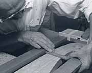
To lay out mortises for bed
fastener hardware, clamp all four legs together with their feet
flush, and use a marking knife to get a crisp
line. | |
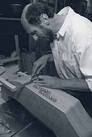
I did all the mortising on a horizontal mortiser, transferring the scribe lines from a bedpost to the fence of the mortising table. Then I set my stops and proceeded to cut. Because the bed hardware was about 7/8 in. wide, I used a 1/2-in. bit. I flipped the posts and rails over to make two overlapping cuts, which ensured a centered cut. Next I squared the ends of all 16 shallow mortises with a chisel and marked and mortised the deeper slots to accept the rail pins. The routing and inlaying could be done with a router and jig.
Before attaching the hardware, I checked mating pieces for a fit. I noticed about 1/32 in. of side-to-side play -- very little really, but for this situation, still too much. The hardware had to align the rails perfectly flush with the posts so the moldings would line up. To remedy this situation, I took a metal punch and pounded a dimple on either side of the slots. It worked perfectly. Absolutely no play. With the hardware in shape, I drilled pilot holes in all the posts and rails and screwed all the bed fasteners into place.
Before gluing anything, I dry-fitted the entire bed to be sure that everything was in order and that the rails were interchangeable. Then I disassembled the bed and sanded all the parts to 320-grit.
Gluing up the head- and footboard assemblies
I set one post flat on a piece of carpet on the floor and another on a sawhorse within reach. I spread glue into the two round mortises for the crest rail and the two long mortises for the lower rail. Then I set the headboard panel into position, leaving a 1/2-in. gap at both the top and bottom of the groove. The headboard and footboard panels are not glued in; they must be free to expand and contract with seasonal changes in humidity. Holding the panel with one hand, I first slid the crest rail and then the lower rail into their mortises. Then I lowered the opposite post onto the lower rail and manipulated the crest rail into position. Before pounding the post home, I made sure that the headboard was centered in its groove. I pounded the post home, laid the unit gently down on its back and clamped it.
To make sure the panel's edges wouldn't be exposed when it contracted in the winter, I drilled counterbored holes into the posts at midpoint along the groove. I screwed the panels in place and plugged the holes. This ensured that the headboard panel would remain centered between the rails and that they would expand evenly top to bottom. Once both head- and footboard units were assembled, I pinned the tenons of the lower rails and screwed the crest rails through the posts with 2-in. drywall screws, just off center, to reinforce the mortise-and-tenon joint. Finally, I sanded the posts flush with the lower rails where they meet.
Molding and rosettes finish the bed
Before attaching the two bands of molding, I made sure that the rails were firmly seated all the way down in the hangers. It would be embarrassing to have the molding glued on only to have one section of the rail drop 1/4 in. when the box spring was set in place.
Attaching the molding is pretty straightforward, but a few hints are in order. I did the top of the end rails first because it's the most difficult to attach. I fit, mitered, drilled brad holes about 8 in. apart along the center and glued and attached the molding with brads. The molding here is virtually impossible to clamp.
The short pieces of molding across the grain of the posts needed special attention because the post will change slightly in width. My posts were at about 11% moisture content. To allow for some shrinkage, I left about a 3/32-in. gap between this short piece and the side-rail molding. I tacked down this short strip with a brad at either end and one in the middle, and glued about two-thirds of the way from the miter to the end. The side rail moldings were cut to precisely the same length as the rails and glued using spring clamps and bits of molding cutoffs turned upside down to spread the clamping pressure. The procedure was the same for the lower band of molding.
To support the box spring, I marked and routed mortises for short (1-1/4 in. wide) sections of 1/4-in.-thick, 4-in. steel angle iron I had cut for that purpose. I screwed those brackets directly to the side rails.
The crowning touch was attaching the turned rosettes. I drilled a 3/32-in. hole into the center of the back of the rosette, tacked in a snipped off piece of 6d finishing nail to center the rosette with the post hole, and glued and clamped the rosette.
The bed was finished with three coats of Tried and True varnish oil (available from Garrett Wade; 800-221-2942; http://www.garrettwade.com/). This is the only pure linseed oil on the market, with no additives or driers. It requires a good deal of elbow grease to wipe off, but the build and depth of shine is worth it.
For the record, the bed was completed in 96 hours.
| From Fine Woodworking #124, pp.
54-61 Purchase back issues |