Curved Cope and Stick Joinery With Stock Router Bits


Requirements For This Project You'll need two routers in router tables to do this procedure, as well as a small band saw and a table saw. Also required are the following router bits- a straight fluted flush trimmer, a rabbeting bit that matches the sticking depth and a set of cope and stick cutters. The latter will cost around $75. Your stock must be flat to do this work precisely. Using a jointer and planer to flatten stock will help tremendously. Otherwise, pick stock very carefully for flatness and uniformity of thickness. Other useful items are trammel points and a radius jig. Isn't that an awful looking shirt?

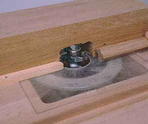
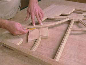
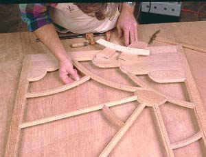
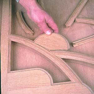
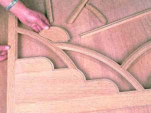
'COPE AND STICK' JOINERY (or 'stile and rail') is a very common means of making wood frames for glass or wood panels. Large window and door shops use this technique with expensive shapers and molders for producing large runs of square sash and doors, as well as some curved pieces. Cabinet shops do the same thing for kitchen cabinet doors, often using router bits. Using such bits you can do the same thing in your shop for making cabinet doors with wood panels or glass. Here we are going to focus on using such bits for the purpose of making curved components for a cabinet door in which there will be glass, or wood panels if you like.

These are advanced router techniques. They can require that you cut very small parts on the router table, as well as climb cut against the grain. There are safe ways to do both of these, but it will be easier and safer if you have a few years experience doing various router work. If you are newer to routers, I suggest you use a design that incorporates larger parts with larger radii, since these present less of a problem.

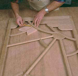
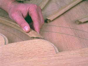
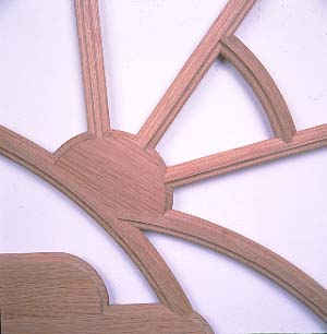
"Sticking" refers to the molded edge along the inside of a door or window frame. We use a "stuck" edge because it looks better than a square corner, but it creates the technical problem of how to join the molded profile at the corners. Through the centuries craftsmen have used a variety of hand techniques to do this. The solution used in the machine age is a variation on one of those, which involves cutting a "cope" into the end of any part that butts up against the edge of another part on its sticking. The cope cut is an exact negative profile of the sticking and fits closely over it (see drawing #1). The result at the corner is a tightly fitting joint.

Handplanes were used to do this, and these were replaced with spinning steel knives on shapers or specialized machines like tenoners, and later carbide cutters for both shapers and routers. The handplane method, to my knowledge, is only capable of cutting straight sticking and copes unless you make specialized handtools to accomodate curves. But with guide bearings on shapers and routers it is easy to cut both sticking and copes along curves. This capability gives you almost infinite design freedom. If you can draw it, you can make it. This is true with the one limitation that parts must have a minimum width or else there is little or nothing to join.

STEP ONE- CHOOSE YOUR BITS

REVERSIBLE BIT SET
This is a typical reversible set. You get one cutter that cuts both the sticking and the cope, and one slot cutter for cutting a panel groove. Some manufacturers offer an additional kit with one more slot cutter which allows you to cut a rabbet below the sticking instead of a slot.

There is a wide variety of bits and shaper cutters available that cut cope and stick joints for cabinet dimensioned stock (3/4" standard thickness). These cutter sets are often called 'stile and rail' sets. While you can do this work on a shaper, I suggest you use router bits. Dealing with small parts on a shaper is less easy to do safely when using a guide bearing and no fence. Also, shaper cutters have a greater diameter and so cannot handle the smaller radii cuts that router bits can. I would only do this kind of work on a shaper with a project design that has large parts with large radius curves.

Your bits must be capable of executing the steps shown in drawing 1. All of the available bits will cut a profile that leaves a panel groove as is required for kitchen cabinet doors. If you want to install glass however, you must be able to leave a glass rabbet below the sticking so that glass can be placed and replaced as needed.

Standard bit sets are intended to cut both the sticking and rabbet on part edges simultaneously. While this works fine on large, straight parts it is foolish on small, curved parts. Get a set that will do the two separately. Sets with stacking cutters allow you to arrange the different cutters as you wish for specific operations. Non-stacking, or integral cutters won't do this and are therefore a bad choice for this work.

The least expensive way to go is with a set of reversible stacking cutters, which use the same cutter for both the sticking and cope cuts. That cutter is used in combination with rabbeting cutters and a guide bearing to execute the necessary steps. I used an Eagle America #184-0305 reversible cutter which has a 1/2" shank arbor, along with a #100-8420 accessory kit which gives the set glass rabbet capability. (Eagle America, P.O. Box 1099, Chardon, Ohio, 44024. 1-800-872-2511). There are other bit sets from other manufacturers that will do the job just as well (click here). Be sure that the set you get will make a glass rabbet rather than just a groove for a wood panel.

A reversible set is the least expensive way to go, as well as the least versatile. Because the cutter must cut both the cope and the stick shapes, it must be symetrical, limiting your profile choices. As well, you must reconfigure the stacking cutter between cope and stick cuts. It's a lot easier if you have one bit for cope and one bit for stick, and set them up in separate router tables. (A third router table with the rabbeting cut in it would be nice too- if you have it!) In this way you can make test cuts until all the setups are as you want them, then leave them set up as you do all the work.

Note that some sets cut a panel groove or glass rabbet that is recessed behind the upper lip of the sticking (drawing 1D). These sets can be used for these procedures, but further complicate an already involved situation with different radii and rabbets. I recommend a set where both the rabbet and sticking upper edge are an equal distance from the outer sticking edge (as depicted in drawings 1A, 1B and 1C).

STEP TWO- MAKE A DRAWING

The fanciful design of the door shown here incorporates most of the procedures you might encounter building different designs. Depending on how elaborate your design is, you may have to improvise in certain situations. Note that all of the curves in my design are radiuses, and none are free-drawn lines. This makes the procedure much easier because you can quickly and accurately make templates by arcing with a router. But if you wish you can make templates to free-drawn lines by cutting them out on a band saw and sanding smooth. This will necessitate making matching coping templates by hand which, again, is more difficult than arcing on a router.

Photo 1- A full scale drawing is essential for
aligning the curved parts. Strike arcs with a
set of shop made trammel points.

You can buy a set of trammel points by clicking here.

The minimum width of the parts on my door was limited by my cutters. The sticking and rabbets are 3/8" deep on the cutters, and any given skinny part must have that on each side plus something in the middle. Thus 1" wide parts gave me a 1/4" center section, which is minimal but adequate. Once I had finalized my design, I made a full scale drawing of it on a sheet of plywood (photo 1) using a set of trammel points for striking arcs. This full scale drawing is essential for aligning parts during the procedure.

STEP THREE- MAKING TEMPLATES

Two different types of templates are required; one group for flush trimming to the outside of the sticking (sticking templates), and one group for flush trimming to the outside of the cope (coping templates). Refer to drawing 2 to see the difference. When you cut a sticking into a curved part edge, two radii are created. The first is the outer edge of the sticking itself, and the second is the edge of the rabbet beneath, which will be greater or lower than the sticking radius by the width of the sticking itself. Whether it's greater or lower depends on whether you have an inside or outside curve.

When you flush trim the end of a part that will butt up against a curved part edge, the radius of curvature along the end of that part must match the radius of the rabbet it meets, not the outside of the sticking. It is the rabbet that the part will hit, except along the cope. The template you use to flush trim the end of the part is called the coping template, because it establishes the surface that will be coped (see drawing 2).

To start my door, I made a list of templates needed, beginning with sticking templates which were to the sticking radii I had drawn on the full scale drawing. Next was a coping template to use wherever any part butted up against the edge of a curved part. (Where a part butts up against a straight part, the end is straight and so is the template required.) But more coping templates are required for making curved cope blocks that fit onto a curved sticking to back it up on the end while the cope is cut (more on this later-but look at photos 16 and 17 to see cope blocks in use). All in all I needed close to 20 separate templates.

Photo 2- Make a list of templates from the
arcs in your drawing, including both
sticking and coping templates (see text).
Use a router radiusing jig and straight
flute bit to arc out the templates.
Photo 3- Nest the templates together
as best you can on your plywood
so you waste a minimum.

To see a router radiusing jig, click here.

Once I had my list of templates, I set up a router arcing jig (photos 2 and 3) to cut them out. That jig pivots the router around a nail that is driven into the 1/4" Baltic birch plywood template stock. Note that for an inside radius you must measure to the outside of your straight flute bit, and for an outside radius you must measure to the inside of the bit. For the smaller radii I set up on the router table as in photo 4.

Photo 4- Make smaller templates on
the router table with a simple pivot
location setup.

To see router tables click here.

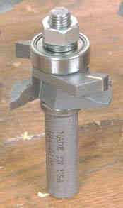
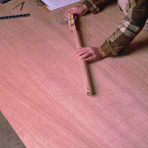
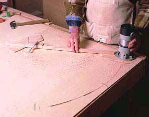
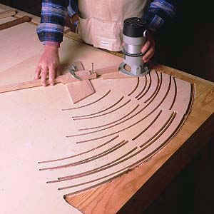
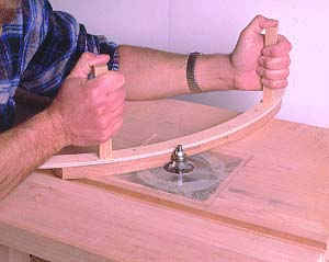
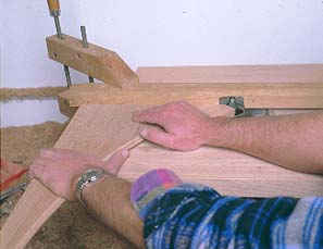
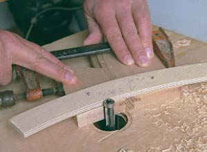
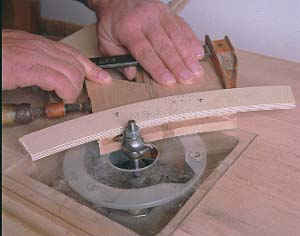
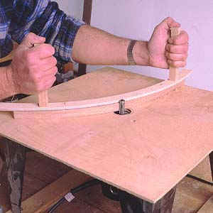
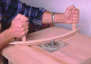
Photo 5- Flush trim parts to the sticking templates. Install safety handles on the templates with countersunk screws so that you can keep your hands away from the bit. Climb cut against the grain by applying firm pressure down on the table with the safety handles, and take light slow cuts.

STEP FOUR-S4S (surface four sides)

I ripped to width the straight parts at the table saw, and did the equivalent on the curved parts at the router table with a flush trim bit and the sticking templates (photo 5) after band sawing away the waste close to the template. Because the parts and templates are small I screwed safety handles onto the templates to keep my hands above the bit. To orient the location of the template on the top rail, I placed the rail on the full scale drawing in location as shown in photo 6. Then I placed the template on the rail, positioning it by eyeballing with respect to the curved line on the drawing. It is not important that the template be located on the rail at exactly where it is on the drawing, just close.

Photo 6- Align the template for a curved
top rail by placing the rail on the full
scale drawing and locating the template
on it using the drawing. Flush trim the top rail.

I attached the templates to the parts with short nails. Wherever possible, I attached the templates to the back of the parts so the nail holes would not be seen. On some parts I was able to locate them on ends that would later be cut off. But on one part, the sun arc, I was forced to drive two nails into the face during the final coping cut so that I could attach a handle for safety. In this case puttied nail holes were the price of safety.

STEP FIVE- STICK AND RABBET

Your bit set is designed to cut both the sticking and rabbet simultaneously, but for this procedure I did both separately because of the small size of the parts involved. With the parts still attached to the templates I cut the sticking profile into all the parts (photo 7). The bearing doesn't ride on the template for this step, but I kept the templates attached solely for the safety handles.

Photo 7- Cut the sticking shape into
all parts. Note that the bearing rides
on the part edge, not the template.
Attach the template to the parts for
the sake of the safety handles.

On curved parts such as these, there are invariably sections where the router is cutting against the grain. If you feed the part into the cutter against its rotation on these sections as one normally does, tearout will result. The solution is to cut these sections by feeding the part into the bit with the rotation of the cutter, called "climbing the cut." This is potentially dangerous because the cutter can grab the part and throw it. However, by following three rules I was able to do this safely;

-Always use safety handles attached to small parts.

-Apply firm, even pressure down onto the table throughout the cut.

-Make the cut in a series of light passes, 1/8th inch or so.

After I cut the sticking into all parts, I prepared to cut the rabbets. First, however, I set up the coping pass in order to get an example of the cope cut. This I used to adjust the height of the rabbet cutter for the rabbeting pass. This height determines the thickness of the sticking, and thus the fit of the sticking in the cope (see drawing 1). It is easier to adjust the thickness of the sticking to fit the cope than vice versa. This fit is critical because on many parts this is the entire joint.

Photo 8- After cutting the sticking,
set up the cope to get an example of its
cut. Then use this example to adjust the
height of the rabbeting cutter, and rabbet
all parts again attaching the templates and
safety handles.
Photo 9- Attach whatever is necessary to
smaller parts to guarantee that you can
make the cuts on the router table safely,
even if it means driving nails into an
exposed surface.

Using the cope cut example I set up the rabbet cutter to the correct height, then re-attached the templates to the parts and cut the rabbets (photo 8). In this pass the bearing rides on the outer lip of the sticking, so again the templates are just there for the safety handles. For small parts attach whatever templates or scrap pieces are necessary in order to make the cut with your hands away (photo 9).

Photo 10- Thin parts will rock against
the fence when the rabbets are cut out
as there is less material left for support.
Install a support block that contacts the
new surfaces after they are cut, and don't
pass your fingers over the cutter.

Cutting the rabbets into both sides of skinny straight parts, like the sun rays, is tricky because the parts can rock as they are cut. I solved this by attaching a support runner to the router table on the off-feed side (photo 10). This piece supports the part within the rabbet after it is cut. I always kept my fingers at least six inches from the cutter.

STEP SIX- COPE

Next I set up the cope at the router table, carefully adjusting its height to match the location of the sticking on the parts (jump ahead to photo 18). I also set up a second router table with a flush trim bit. This second table is necessary because the cope procedure requires that you go back and forth between a flush trim cut and a cope cut, and you don't want to be changing bits every five minutes. Also, once the cope is set up, you don't want to change it. By not changing it you ensure that all the cuts made with it will be exactly the same.

Photo 11- Set up the cope, and make
cope blocks that fit against stuck edges
to back up the cope cut on the end of
the part. For straight ends, such as
the top rail, scribe the line of the rail
end onto the cope block. Flush trim to
that line.
Photo 12- To cope the rail end, install
a straight fence on the cope setup, and
push the part along it with the cope block
in place to back up the cut.

For the cope on the top rail, I first cut out a cope block to back up the sticking during the cut. Using the cope block template with a radius matching the rabbet radius of the top rail I flush trimmed the cope block to the template, then coped it on the other router table with the cope cutter. Next I placed it on the sticking at the end of the rail (photo 11) and scribed a line across its top to continue the straight line of the rail end. Then I removed the cope block and flush trimmed to the scribed line by attaching a short, straight length of plywood to the cope block with nails. This short piece of plywood is the template that the flush trim bearing rides on. Finally I attached a straight fence to the coping router table and pushed the rail end through the cut, holding the cope block to the sticking during the pass to back up the cut and avoid tearout on the sticking (photo 12).

Photo 13- Join the door frame rails
and stiles with loose tenons. Cut slots
for them on the table saw with a tenoning
arrangement. Glue up the frame.

With the top and bottom rails coped, I cut slots for loose tenons in the rails and stiles and glued up the frame (photo 13). I made these cuts on the table saw with a tenoning jig, but you could also do them on the band saw referring to a fence. Keep the cuts below the sticking. Next I cut copes on the five bottom pieces to fit them to the bottom rail, stiles, and each other and glued them in place. When I needed to apply clamping pressure to an edge with sticking, I made cope blocks, put them on the sticking, and put the clamp on the block.

Thus far all the copes have been on straight edges cut at 90o. For the curved internal parts, many copes will be along curves joining at odd angles. To orient these parts, I used the full scale drawing.

Photos 14 and 15- Place the frame over the drawing, suspending it above
with spacers. Place curved parts beneath, with cope blocks on both sides.
Align curve part relative to frame and previously fitted parts using drawing.
Scribe rabbet arc from fitted part onto cope blocks of new part below.

Each curved joint must be done separately. Lets look at how I did one to see the procedure used for each. First I made cope blocks to fit on either side of the part to be coped. Then, along with the cope blocks, I located that part in place on the full scale drawing. Next I placed the door on top of the part, suspending the door at its corners with blocks (photos 14+15). I located the door directly over its corresponding lines on the drawing. With the parts located this way, the rabbet on the part that is being joined to is now lying in location directly on top of the part about to be coped and fitted to it. I made one final check to see that all parts were aligned and then scribed the line of the rabbet across the top of my parts cope blocks and the part itself (photos 14 and 15).

Photo 16- Remove frame, place coping
template on scribed line. This template's
radius matches that of the rabbet that the
part will fit to, though it is a negative
profile. Nail the template in place to
the cope blocks and squeeze it all
together with a clamp. Band saw away the
waste.
Photo 17- Flush trim to the template.

Removing the door, I then placed the coping template that matches the rabbet radius of the joining part onto the line I had scribed, and nailed it to the blocks (photo 16). A clamp holds it all together. Then I band sawed away the waste, and flush trimmed to the template (photo 17). From there directly to the cope setup (photo 18), and voila, curved coped component.

Photo 18- Cope. Voila.

To fit the other end of the piece I duplicated the process, with the added detail of butting the already coped end against the rabbet of its joining piece. In practice it helps to cut out the parts a bit long at first, see how they fit, and shorten them if necessary by repeating the flush trim and cope steps with the part in the cope blocks as before, but protruding just a hair so that it is shortened by the flush trim and cope cuts.

Note that the cope blocks serve several purposes. They give you something to attach the coping template to. They back up the cope cut so the sticking won't tear. They give you something large to grab as you cut the piece on the router tables. And, they provide the surface that the coping cutter bearing rides on as it makes the cut into and out of the part. This last point is critical because if the cope blocks arent wide enough in the area that gets flush trimmed, the outer edges of the sticking will not be cut along the intended line. This will make gaps right where they will be seen, defeating the whole purpose.

PROBLEMS AND SOLUTIONS

Because of slightly warped stock, the sticking thickness on some of my parts varied as the heights of the sticking and rabbeting passes varied. Thicker sticking means the cope won't fit. You can widen a tight cope by chiseling away a thin layer along the flat surface of the coped profile that contacts beneath the sticking in the rabbet.

The cope blocks are supposed to back up the cope cut as it is made, but if they are at all loose or your wood is brittle you will still get tearout, again, right where it is seen. If this is a problem put masking tape on the sticking at the point of the cope, so that the fit against the cope block is very tight at this point. You want to pinch the wood at the point where the cope cutter comes out of the cut on the sticking and into the cope block. Focus on the pinch points and youll avoid tearout.

Note that it is hard to locate parts exactly where they are supposed to be on the drawing. But note also that it is more important that each part meets joining pieces tightly rather than being located exactly. Because the shapes are irregular you have a fair fudge factor in locating parts. The drawing is a general reference, the fit of copes is what must be precise.

If your sticking templates are from free-drawn lines rather than specific radii, make coping templates by scribing a template directly from the line of the rabbet to which parts will join. Band saw the template, and hand sand to fit the rabbet. A small drum sander in a drill press is real handy here. How well the template fits the rabbet determines how well the part will fit. Note also that the part will fit in only one spot, you can't slide it along the curve as you can with a specific radius. You have less fudge factor with free-drawn lines.

The small parts are too small to join with dowels or tenons. The odd angles would further complicate any such attempt. But, the copes will keep the parts locked in place. Glue the parts in, or use epoxy if you wish, but remember that cleaning squeezed out epoxy from little corners is very difficult, whereas hot water and a stiff brush get glue out in a hurry.

Cut glass to fit the rabbets, and hold it in with glazing compound or silicon caulk. The latter holds like glue and will contribute to the overall strength of the small and weak joints of the internal components. Glass in such doors becomes a structural element to a certain extent. The four main corner joints are what hold the outer frame parts, but the glass can play a significant role holding together small wood internal parts and you might as well take advantage of that with caulk that works like a glue.

If you choose to make your parts with a panel groove instead of a glass rabbet, dry assemble the door and scribe templates for your panels by tracing to the arris of the sticking and part faces. This line is the same as the bottom of the rabbet, and shows the shape that the panels must be. Cut your panels slightly smaller than these lines, raise them if you wish, and install them when you glue up the frame.

But it is best not to glue up all these small internal parts in one large glue up. Glue each part in place as it is made, before you fit the next part to the first. This is because you can easily change the location of one part during the glue up, which will mess up the fit of the next part which rides against the first. If you make panels, though, this means making and gluing each panel in place as the parts that surround it are finished. If you have a lot of small internal parts with panels, this is really the only way to go to ensure that everything will be well aligned. With glass, you wait to cut and fit the glass until the whole door is fitted and done. Don't cut your glass according to your drawing, because the final fit of parts will vary from the exact locations of parts shown on the drawing. Use the finished door to trace templates on paper, or directly onto the glass, for cutting.

Call a local leaded glass artist to find out where the best place is in your area to buy stained glass, if that is what you want. Note that stained glass suppliers also have different kinds of textured clear glass which looks antique. But watch prices- some glasses are outrageously expensive while a similar looking glass may cost half as much or less. Standard window glass (called 'float') is the least expensive but has no texture or character. Have a stain glass maker cut the glass for you if you are nervous about it. Do all your finish work on the wood before installing the glass. Glue the glass in place with silicon caulk, then fill the rabbets with glazier's putty for wood frames. You can color the putty with paint tints like Burnt Umber to approximate wood color. Flatten the putty in the rabbet by drawing a flat tool such as a putty knife across it. There's a trick to this which you will just about master by the time you finish your frame.
Hosted by uCoz