Shining showcase
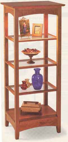 |
Bring your special glassware, chma figures, or other prized
collectibles out of the closet and into the light. This easy-to-build
project showcases their beauty and your craftsmanship.
Here's a visually high-impact piece of furniture that you can build for
only a moderate investment of time and materials. Its three glass-insert
shelves let light from a concealed halogen fixture stream from top to
bottom.
To discover how to beef up frame corners on this project and others, see
the mitered half-lap joinery article on page 16. This joint hides the
frames' exposed end grain within the project's legs.
|
Laminate four legs
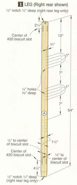
1 Cut eight 3/4 x l 5/8 x 55"
blanks for laminating the legs (A). To form a channel to conceal the light
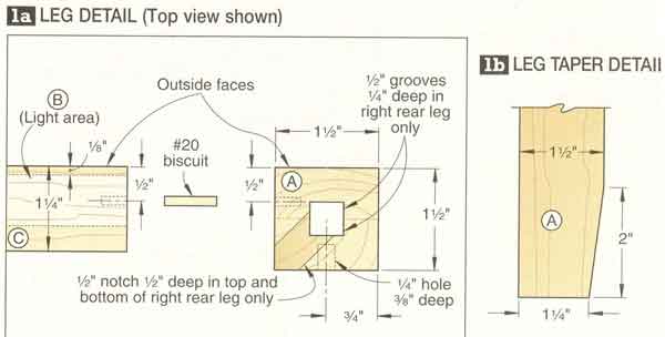
fixture's cord, install a dado blade in your tablesaw, and plow a centered 1/2"
groove 1/4" deep in two of the pieces, where shown on Drawing 1a.
2 Glue and clamp four pairs of
laminations, keeping the ends and edges flush. The grooved pair forms the right
rear leg. Remove any excess glue, and joint 1/16" off one edge of each
lamination. Plane the opposite edges to form four 1 1/2 x1 1/2" legs. Trim the
legs to the length listed in the Materials List.
Ç Ìàrê the tops of the legs with
their final orientations. Indicate the face to be drilled for shelf supports.
Position the leg with the centered cord channel at the right rear, where shown
on Drawing 2. Referring to Drawing 1, lay out the shelf-support hole centers on
the right rear leg.
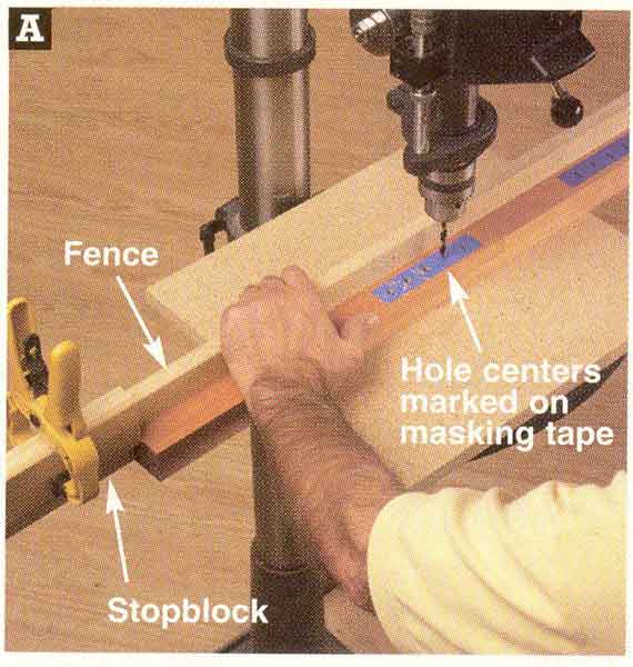
4 To drill the legs' shelf-support
holes, chuck a ]A" bit in your drill press. Attach a 5'-long fence 3A" back from
the bit's center, with about à of the fence extending to the right of the bit.
Drill the ys"-deep holes, as shown in Photo A.
5 Adjust your biscuit joiner's
fence to center a slot 1/2" from the legs' outside faces, and cut slots for #20
biscuits, where dimensioned on Drawing 1.
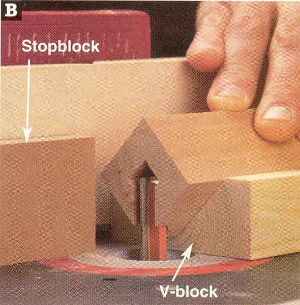
6 To provide electric cord access
to the hole in the right rear leg, make a V-block from 2x4 scrap. With a 1/2"
straight bit in your table-mounted router,
and a stopblock clamped to the fence, form a 1/2"-long notch in the leg's top
and bottom inside corners, where shown on Drawings 1 and 1a and as shown in
Photo B. Cut the notches in steps, first positioning the bit to cut 1/8" into
the leg's corner, and then raising the bit in 1/8" increments until the notches
are complete.
7 Mark the bottom tapers on each
leg's two inside faces, where shown on Drawing 1b. Bandsaw and sand to the
lines. To ensure uniform tapers, see the Shop Tip at right. Sand the legs to 220
grit.
 |
 |
 |
 |
| Mark the right-rear leg shelf-support hole centers on
masking tape. Align each mark with the bit, and position a stopblock.
Drill all four legs at each stopblock position. |
With the right rear leg cradled in a V-block, rout the top and
bottom 1/2"-long notches in progressive 1/8" increments. Clamp a
stop-block to the fence to control the depth. |
|
Shop tip |
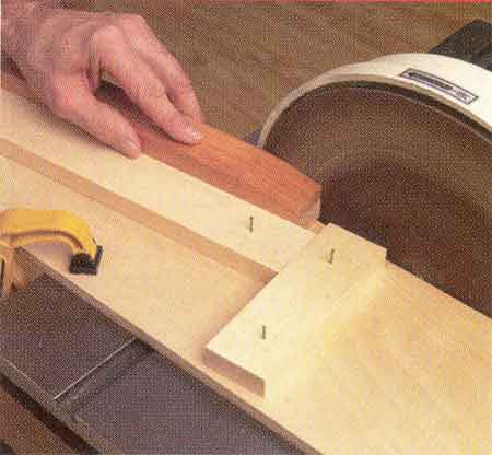 |
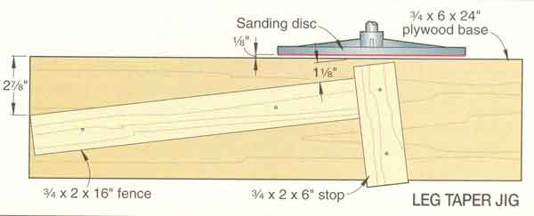
To sand uniform tapers on all four legs (A), tack
together the scrapwood jig shown in the drawing, below. Leave the
nailheads protruding so you can easily disassemble the jig and return
the parts to your scrap bin. Clamp the jig to your disc- or belt-sander
table 1/8" from the face of the sanding disc. Slide each leg along the
fence, as shown in the photo, right, until its end contacts the stop. |
 |
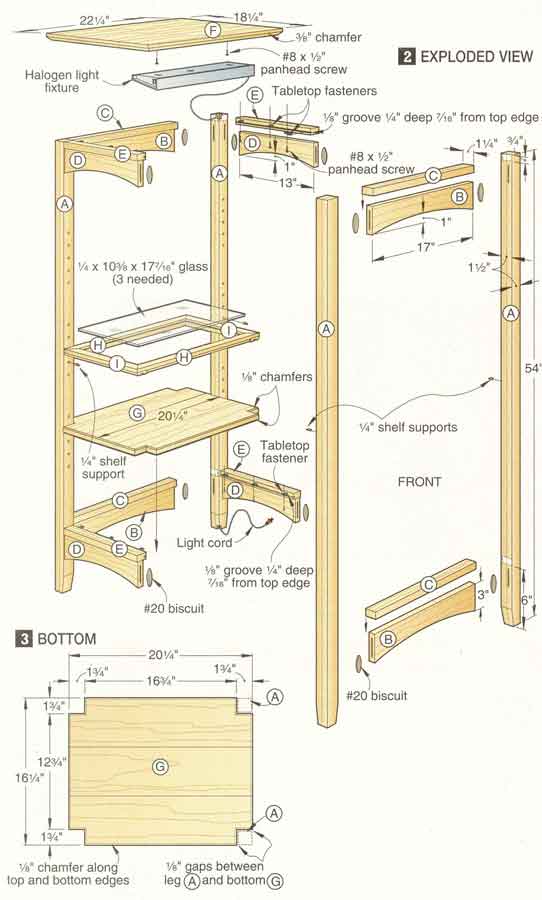 |
Form the rails and caps
1 Cut the rails (B, D) and caps (C,
E) to size. To ensure that the rails and caps are identical lengths, use
a stopblock clamped to an auxiliary miter-gauge extension.
2 Adjust your biscuit joiner to
center a slot in the thickness of the rails. Then plunge slots for #20
biscuits in the rail ends, centered in their width.
3 Using a fairing stick,
draw arcs on the rails (B, D), where shown on Drawing 2. Saw and sand
them to shape.
4 Cut 1/8"
grooves 1/4" deep for the tabletop fasteners in the side caps (E), where
shown on Drawing 2. Note: Before cutting the grooves, check the offset
of your tabletop fasteners. It may be different from the 7/16" dimension
shown on the drawing.
5 Finish-sand the rails and
caps. Mark the locations of the top edges of the rails (B, D) on the
legs (A), where shown on Drawing 2. Glue, biscuit, and
clamp the front and back rails (B) between the front and back legs. Then
join the front and back leg/rail assemblies (A/B) together by gluing and
clamping the side rails (D) in place. Glue and clamp the rail caps (č,
┼) to the rails. The caps' front edges are flush with the legs' outside
faces. Finally, ease the corners of the completed assembly with a
sanding block.
|
 |
 |
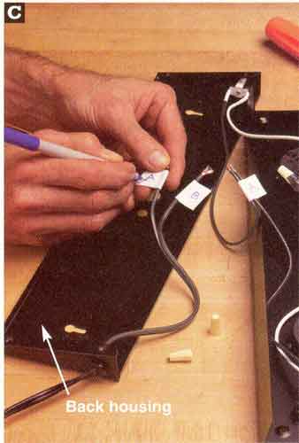
Disconnect the cord from the internal wiring by removing the wire
nuts. Mark the wires for proper reassembly.
|
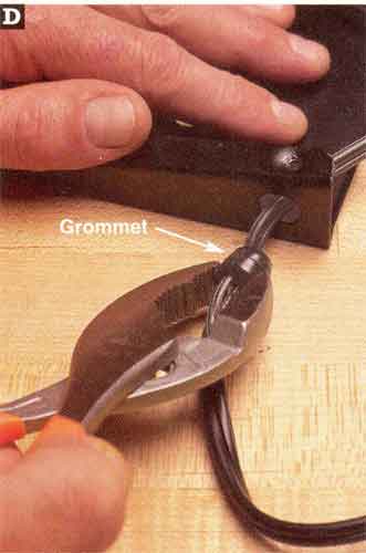
Grasp and squeeze the cord grommet with pliers to release the cord
from the housing. Pull the cord out of the housing, and remove the
grommet.
|
