Joining Wood
|
|
How many things are single pieces of wood?
The elements of joints
I shall not attempt to catalog or discuss all the joints in woodworking.
Rather, 1 shall discuss the four critical considerations lhat determine the
success ofl any given joint. One of the four may be of overriding importance in
some particular situation, or any one may be interrelated with one or more of
the others. These four basic considerations are the stress system involved, the
grain direction of the joined parts, wood movement in re-ing parts.
The stress system is what the joint is being asked to do mechanically, as a
consequence of its being part of a
sion, shear or racking (bending), and usually the great difference in the
strength of various joints depends on the stress situation. Most compression
joints give little trouble, and shear stress is not too difficult to overcome.
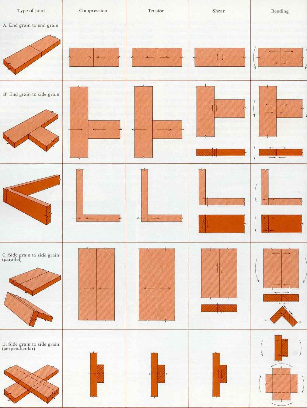
Joints subject to tension and racking are usually the most troublesome. Figure 1
shows joints under representative stress systems. Although it is not usually
necessary to figure the loads precisely, one must have a general grasp of the
direction and relative magnitude of stress in order lo design and construct good
joints. This analysis can come only from realistic examination of the structure
tn which the joint will be used, and the loads it is likely to encounter in
service.
The second element is the grain direction in each mating surface of the
joint, as related to the stresses involved. For example, the most difficult
surface combination to fasten is end grain to end grain (1A). It would not
matter if the load were exclusively compression, but this is most uncommon
without some racking stress also. As a result, limber framers who must often
lengthen stock to span a space have evolved an elaborate system of scarf joints,
many with mechanical interlocks, whose principal purpose is to convert mating
end-grain surfaces to long-grain surfaces. End grain to side grain (1B) is a
very common situation, which can be accomplished quite satisfactorily if all
factors are considered. When stressed in compression, such a joint is usually
limited by the perpendicular-to-grain compression strength of the side-grain
piece. When stressed in tension, the fastening to the end grain may be
difficult, and when under racking slresses, either part may be the limiting
factor. The solution usually involves a mechanical interlock formed on the
end-grain piece or made by adding a third piece of wood to cross the joint.
Side-grain to side-grain joints (1C.D) can be as strong as the wood itself when
they are adhesive-bonded, even when the grain directions of adjacent members are
not parallel. But here the third element comes strongly into play, the
dimensional properties of the wood in response to
changing moisture conditions.
Dimensional change in response to moisture is usually no problem in the case
of end-grain (1A) or parallel side-grain to side-grain joints (1č) because the
orientation of the growth rings can be the same in boih pieces. In these same
joints, if the growth rings are not similarly oriented, the difference between
radial and tangential movement might cause visual difficulties, if not
structural problems.
In perpendicular side-grain to side-grain joints (1D) and in end-grain to
side-grain joints (1B), the conflict between dimensional change along the grain
and across the grain (especially where tangential direction opposes longitudinal
direction) may become more important than the stress/strength of ihe original
joint. The potential self-destructiveness of such joints should always be
anticipated, A lap joint (1D), for example, might be very strong when glued, but
it could self-destruct as a result of dimensional change.
The last element is the surface condition of the mating parts, including the
precision of fit and evenness of bearing, the trueness of the surfaces, and the
severity and extent of damage to cell structure resulting from the surfacing
process. Uneven surfaces may concentrate enough stress to overcome the strength
of wood or glue, while the same joint would survive very well if it had fit
properly. Poorly fitted parts may also allow unintended motion, ending in
destruction. It is quite common for joints to fail not along a glueline, but in
adjacent wood tissue that had been mangled by poorly sharpened tools or bad
woodworking technique while the joint was being cut. In joinery, the
combinations of stress, strength, dimensional change and surface quality are
endless. But careful analysis of the factors involved in each joint will develop
your judgment and minimize your mistakes. I'll discuss a few of the more common
joints, to suggest how you might approach your particular joinery problems.
| Basic types of joints The term joint has various and sometimes overlapping meanings. In its broadest sense, it refers to any junction between two components or materials. Without reference to any accompanying means of fastening, joints can be characterized on the basis of the grain orientation of the mating surfaces as end to end, and end to side or side to side. Flat mating surfaces are loosely termed butt joints, although this term usually suggests either end-to-end butt joints (1A) or end-to-side butt joints (1B)- Side-grain to side-grain joints are more clearly designated as edge joints when the mating grain directions are parallel (1č) or as lap joints when the grain directions are perpendicular (1D). (The special case for miters and scarf joints would be termed cross grain to cross grain.) Obviously, such joints have no structural integrity without some means of holding or fastening the pieces together. I prefer to consider three basic types of joints or a combination thereoi: Worked joints, where the wood is physically interlocked or fitted together; Fastened joints, where a "third party," the fastener, is attached mechanically to both components; Glued joints, where an adhesive forms a continuous bond between two pieces by surface attachment. Each type has its ancestor far back in history The first worked joints might have been tree stems with forks or splits, interlocked with others, or perhaps circular branches inserted into knotholes. The first fasteners were probably thongs of hide or vines, used to lash wooden parts together. Who can say when the first crude metallic nail replaced a wooden pin to hold two pieces of wood together? Adhesives were probably discovered when residues from cooking meat accidentally stuck two pieces of wood together. Modern fastening systems are refinements of each of these, in complex and igenious combinations. |
 |
Worked joints
Creating interfitting or interlocking shapes to provide strength and
integrity in a joint has been a hallmark of the woodworking tradition. Alihough
modern machines can simplify the making of fitting parts, the pride of
accomplishment in hand-execuiion of difficult and beautiful joints will always
be among the challenges, pleasures and rewards of woodworking.
The mortise and tenonŚFastening of end-grain to side-grain joints can be
accomplished with a high level
of success using the mortise and tenon. The basic join is fashioned by
forming the end-grain component, the tenon, into around or reclangular cross
section and inserting it into a hole, or mortise, of the same size and shape in
the side-grain component. By closeness of fit alone, this joint can have
positive resistance in compression, shear and racking, in which cases the
strength of the wood in compression perpendicular to the grain limits movement
in ihe joint (2). The mortise and tenon is commonly associated with frame
construction. In chairs, round shapes are usually used. In window frames,
paneled doors and other squared frames, the rectangular form is common.
The mortise-and-tenon joint has mechanical restraint in every direction
except direct withdrawal of the tenon from the hole. Although this is the way a
joint usually comes apart, it most often does so only after damage due to
racking. A racking load on a rectangular frame acts to deform it diagonally.
Under racking loads, the tenon pivots in the mortise.
The basic "dry" joint can be improved in several ways. The most obvious is
to glue it, thus adding side-grain to side-grain shear resistance along the
mating mortise-and- tenon cheek surfaces to oppose the rotational effect, A
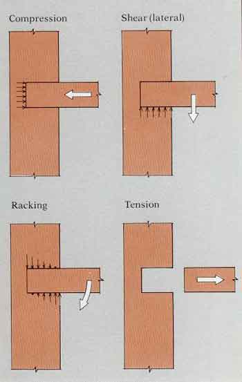
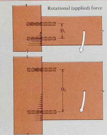
second approach (3) adds a shoulder to the tenon, giving additional bearing
surface to share the compressive resistance on the outside of the mortise.
In our earlier discussion of beam strength (Chapter 6), it is pointed out
that the greater the depth of a beam, the lower the axial stress developed when
the beam is loaded. The mortise and tenon (end-grain to side-grain joint) can be
thought of as a cantilever-beam attachment, so increasing the height of the
"beam" will reduce stress (4). This also increases the surface area of the
cheeks, and thus the gluing area. Lengthening the insertion depth will further
increase the resisting glueshear areas.
 |
|
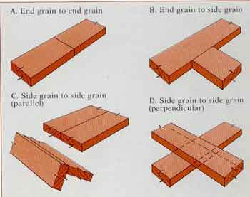
| 2ŚA mortise-and-tenon joint has posilive resistance to compression, shear and racking, even without glue, but no resistance to tension. |
 |
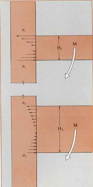 |
| 3ŚIn a shouldered tenon subjected to racking, rotation is restricted by shear strength in the glueline bonding the cheeks of the tenon. The bearing surface of the shoulder carries corn-may open so (ha! shear in the upper area of the tenon (S) will be greater than below (S'). | 4ŚA mortise-and-tenon joint func-lions like a cantilever beam, so increasing the heighl of the tenon will reduce the stress on the joint, if the force (M) remains the same. |
At the same time, the improvement in mechanical advantage obtained by
increasing height is offset by increased dimensional conflict between
longitudinal and transverse grain orientation. Some careful compromises must
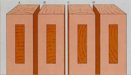
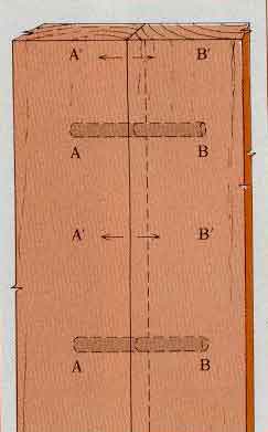
therefore be worked out. For example, since tangential shrinkage (and swelling)
is about twice the radial movement, it is best to have the radial (rather than
tangential) grain direction of the tenon matched to the long dimension of the
mortise. It is also better to have the radial direction of the mortise matched
to the longitudinal direction of the tenon. In Figure 1, joint A would be best,
since radial/longitudinal grain direction is matched along the mortise cheeks
both vertically and horizontally, and tangential grain is matched
perpendicularly to the plane of the mortise. Joint D has the worst dimensional
conflict. As the height of the mortise (along the grain) is increased, joint
survival increasingly depends upon moisture control. The usual solution to
dimensional conflict is to divide
the joint into multiple sections (2). By keeping the dimensions
of each tenon within limits, dimensional conflict can be reconciled by
mechanical restraint. Thus there is considerable advantage, especially in wide
or thick stock, in multiple tenons or multiple splines. These considerations
also emphasize the importance of well-made, well-glued joints designed for
mechanical restraint of the dimensional conflict as the wood moves, as well as
for initial strength.
In summary, the rectangular mortise and tenon seeks to join side-grain to
side-grain gluing surfaces and to offer optimum mechanical resistance by
maximizing the depth of the joint while still surviving dimensional conflict.
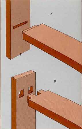
For example, in Figure 3, joint ┬ offers three distinct advantages over joint A.
First, the depth of the individual tenons more than offsets the loss of width.
Second, the height of the glued side-grain surfaces is increased. Third, the
number of side-grain to side-grain interfaces is multiplied.
The round mortise-and-tenon joint has advantages and
disadvantages. By turning the tenon on a lathe and by drilling the mortise,
it can be produced with a high level of precision. However, poor tool geometry
or poor
sharpening commonly leaves drilled hole surfaces and
tenon surfaces in poor condition. The joint may therefore have weak mating
surfaces. Also, the proportion of side-grain to side-grain gluing surface is
somewhat limited and cannot be improved by increasing the dowel diameter. The
best side-grain to side-grain gluing area is located at the mid-depth of the
dowel, where it can do the least for racking resistance.
 |
|
| 3ŚThe multiple tenon (B| is preferable to a single wide tenon (A). Tenon depth more than offsets the loss of width, and the increase in tenon height and the number of side-grain to side-grain interfaces greatly improves the strength of the joint. |
 |
|
1ŚThe best possible orientation of growth rings in a mortise and tenon is
with
radial/longitudinal grain direction matched along the mortise cheeks both
vertically
anil horizontally, as in A. Joinl D, the worst orientation, is apt to split. |
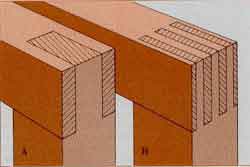 |
| 2ŚAlthough joints A and B have the same amount of wood in each component, joint B has triple the bonding surface and more balanced dimensional restraint. |
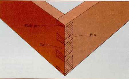
Dovetail joints
Nothing is more symbolic of the woodworking tradition than the dovetail
joint (5). It is a strong and beautiful way to execute the corner side-grain to
end-grain joint and is commonly used in carcase construction. The joint consists
of interlocking tails and pins, giving it strength in tension along the tail
member but not along the pin. It
should therefore be oriented to resist tension against
the tails. In a drawer, for example, the tails should be in the drawer
sides, the pins in the drawer front. In case construction, the pins should be in
the sides and the tails in the top to prevent the sides from spreading. Although
the joint strength results from the wedging action of the tails against the pin
faces, the joint is held in place principally by gluing the side-grain to
side-grain mating faces of the tails and pins. In designing ihe joint, the slope
of the tails must be a compromise. If the angle is not great enough, the
wedging-locking action will be lost. If the angle is too great, the splayed tips
of the tail will be too fragile, and a component of end grain will be
introduced. This impairs the side-grain integrity of the gluing surfaces. An
angle of 11░ to 12░ has proven satisfactory. The joint strength depends largely
on the success of the glue bond between the side-grain faces (the end-grain
areas behind the pins and tails cannot be depended upon for any substantial
contribution to the strength) and the shear strength (parallel to the grain) of
the wood of the tails. Joint strength therefore increases
as tre number of tails increases, as long as anough wood
remains across the narrow part of the tails. However, if the joints are cut
by hand, the added labor should also be considered in determining the number of
pins and mils per joint.
When a large number of pins and tails can be cut with precision, as is
possible with machines, the glued surfaces alone can develop adequate strength.
In fact, the joint can relinquish the wedging taper and have straight tails.
Thus evolved the finger joint or box joint, which gains its strength from the
many closely fitting side-grain to side-grain gluelines.
|
|
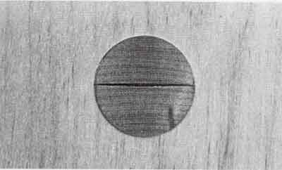 |
| 4ŚIn this yellow birch joint, the tenon was split radially and tangentially before assembly. After moisture cycling? compression shrinkage has developed entirely in one direction, opening the radial split, while the tangentioal split remains tight, and the glueline has remained intact. | |
 |
|
| 5 - The dovetail, a standard carcase joint, has strength in tension along the piece with the tails. |
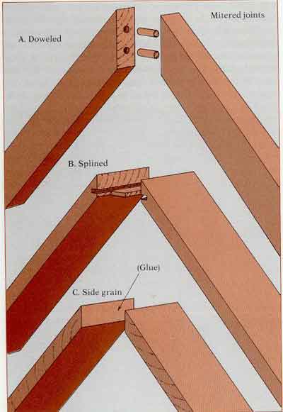
Miter joints
Parallel side-grain to side-grain miters (1č) make a very efficient corner
joint. Miter joints where the grain direction meets at a 90░ angle are
attractive but present serious technical problems. Because of the difference
between dimensional change along and across the grain, the joint may open if the
moisture-content change is great or if the members are wide. If nailed
perpendicular to the outside face of either member, nailing into the end grain
must penetrate deeply to ensure adequate holding. Gluing miter joints is of
marginal effectiveness because of ihe large component of exposed end grain.
Doweled miters, splined miters or combination lap-and-miter joints can improve
strength by providing side-grain to side-grain gluing surface.
 |
|
| 1ŚEnd-grain mitered joints canbe strengthened by dowels (A) or by splines (B). A properly glued side-grain miter (C) will have adequate strength by itself. |
Doweled joints
Dowels are cylindrical wooden rods used in a number of ways to fasten and
strengthen joints. I think of dowels as Tailing into three categories: as
tenons, as pins and as gluing accessories.
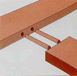
In cases where dowels are used to modify end-grain “Ņ side-grain joints (2)
a dowel is inserted into a hole in the end of the perpendicular member. Since
the piece has side-grain to side-grain contact, a high degree of integrity can
be expected. The dowel becomes a tenon extension of the piece (multiple dowels,
of course, can also be used). The mating hole in the side-grain surface of the
joint becomes a mortise into which the tenon is fitted. In double-dowel joints
that are subjected to racking, one of the dowels carries a critical share of the
load in tension. The remaining load is transferred as surface compression. In
designing such a joint, increasing the height of the member is advantageous,
because it enables the dowels to be spaced as far apart as possible (3). The
design should incorporate dowels that are large enough in diameter to carry
tensile load and deep enough to resist pullout. The dowels should also be able
to carry and transfer the shear load parallel to the side-grain member of the
joint.
This design, when slightly modified, becomes a doweled miter joint, as in
Figure 1A.
Dowels as pins provide physical constraint to a joint without glue (although
glue may still be applied). Examples might include a pinned slip joint, a wooden
hinge pin, the guide pins in a table leaf, flooring pins, etc. Historically,
large wooden dowels called trunnels (tree nails] pinned framing members together
in buildings. The pin usually has ils grain direction perpendicular to the grain
direction of both parts being joined. These parts may have parallel grain
directions but they are more often perpendicular to one another. Pins are
sometimes added as a fail-safe measure or as a way of providing clamping
pressure to draw a joint home. An example of the former is the pin usually
concealed in the neck of a duck decoy, which will hold the head on in case the
neck breaks because of weak grain direction. An example of the latter is the
draw-bored mortise and tenon, where the hole drilled through the tenon is
slightly offset from the one through the mortise, so pounding a pin home pulls
the joint tightly together.
 |
|
| 2 ŚDowels used in end-grain to sidegrain joints in effect become tenons; the mating holes become mortises. |
Despite the obvious success of the draw-bored mortise and tenon, dowels are
most often misused as gluing accessories to hold parts in alignment. For
example, in making a tabletop, boards might be edge-glued and held with a series
of bar clamps. To ensure alignment of board surfaces at the joints, dowels are
sometimes used. However, if gluing is correctly done, full wood strength can be
developed by a plain side-grain to side-grain jointŚno reinforcement is
necessary. Because they do not provide strength, the pins therefore need only be
long enough and numerousenough to ensure alignment. For edge-gluing 1-in.
lumber, 3/8rin. or 1/4-in. dowels that are 1 in. long are plenty. Needless to
say, the holes should be bored a little deeper than the length of the dowels.
Dowels should fit snugly into accurately positioned holes. When the joints are
clamped, no attempt need be made to glue the dowels into the holes in the mating
edges. The loss of glueline due to the dowels is negligible. For example, in
edge-gluing 3/4-in. lumber, a 3/8-in. dowel placed every 8 in. along the joint
reduces the glueline area less than 2%. Although it might seem advantageous to
make the dowels "good and long" and glue them in "good and light," a negative
effect can actually result. The restraint to normal shrinkage and swelling may
cause the wood to fail at or near the glue joint (4), If gluelines fail at edge
joints, the problem should be rectified by trouble-shooting the gluing procedure
rather than by pinning a bad joint with dowels in an attempt to bring it up to
standard. If the gluelines are properly made, there is little to gain in trying
to reinforce the joints, since the strength of the wood on either side of the
joint is still the limiting factor.
Edge joints also are modified by various tongue-and-groove configurations to
assist in alignment. The logic that such joints are stronger because of greater
surface area is questionable. If the quality of gluing is up to standard, the
glueline is as strong as the adjoining wood. In joints of end-grain to
side-grain combination, the spline may become a tenon or a simple locking
device. In edge-gluing, the idea of "strengthening" the joint with a
longitudinal spline may be tempting, but is a serious misconception. Since the
spline is continuous, the reduction in surface area of the board would be
substantial (5). For example, if a 1/4-in. spline ran the length of a 3/4-in.
thick joint, the strength of the joint could be reduced by one-third. If the
spline is very thin and the joint will be subject to bending, only slight
weakening will occur, providing the spline is centrally located along the
neutral axis.
|
|
 |
| 3-In doweled joints subject to racking, increasing the spacing between the dowels reduces the tensile load that each musl carry. |
 |
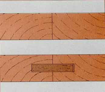 |
| 4ŚIf long dowels are used across an edge joint and glued into (he holes, shrinkage will be restrained across A-B. Tensile stress, will develop across A'-B' as the boards attempt to shrink. | 5ŚReinforcing an edge-glued joint with a cross-grain spline actually weakens the join at the margins of the spline. |
Fastened joints
The term fastener refers to an item that holds together two members being
joined. When used in the sense of a pin, wooden dowels are examples. Other
wooden components, such as cross-battens, corner blocks and plywood gusset
piates, might also be thought of as fasteners. Usually, however, the term
fastener suggests nails and screws. It is likely that when civilization learned
to extract and shape metals, nails and spikes for wood were among the first
items produced. Until the last century, handmade nails had hardly changed and
screws were relatively expensive. Today, however, with automated production,
improved fastener design, and power installation equipment, mechanical fasteners
have become inexpensive and efficient alternatives For assembling wood
components. They are likely to remain indispensable to many forms of
woodworking.
It has been estimated that some 75,000 fastenersŚmostly nailsŚare used in
the average house. Most woodworkers readily appreciate the importance of nails
in general carpentry and softwood construction, but also assume a traditional
notion which holds that fasteners should be avoided in cabinetmaking. But it has
been perceptively observed that wood joints "can be poorly made with
considerable ease," and this would certainly apply to many fastened joints. On
the other hand, fastened joints can also be well made. Woodworkers should
carefully study mechanical fasteners as an alternative means of joining wood.
Since most fasteners are metal and thus have superior strength, failure of
the fastener itself need not be a concern. The primary requirement is holding
power, which is the ability of fasteners to transfer stress from one member to
another without detaching, dislodging or causing failure in either member.
Holding power is closely related to the structural strength properties and
condition of the wood.
Because of the endless array of styles of modern nails and screws, I will
review general considerations making no attempt to summarize the technical data
on individual fasteners.
Nails
TIil' common \„ ire nail, with iis bi uilii Iniish, dumiond-cut point and
flat head, is the most familiar of modern nails. In typical use, it is driven
forcefully and rapidly through one or more materials, embedding its point into
the side grain of seasoned wood. A general empirical formula for direct
withdrawal (1) of a bright-finish, common wire nail immediately after driving,
is:
p = 7,850G 5/2 DL, where
p Ś maximum withdrawal load, in pounds
G = the specific gravity of the wood {Table 3 p. 8)
D = the nail diameter in inches
L = the depth of penetration, in inches, of the nail into the member holding
the point.
Under these standard conditions, direct withdrawal varies directly with the
diameter and length of the nail; the greater the length or the diameter, the
greater the holding power. The formula also reveals that denser woods develop
greater holding power.
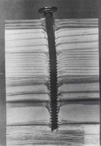
When a nail is driven into a side-grain surface, the longitudinal cell
structure is separated or split apart and also compressed ahead of the point,
depending on its taper or blunlness. As the nail progresses, many cells in the
path of the nail are broken, and their severed ends are bent and compressed in
the direction of driving. The tendency of the cell ends to recover causes them
to press against the nail surface, resulting in resistance to withdrawal.
Withdrawing the nail restraightens the cells,
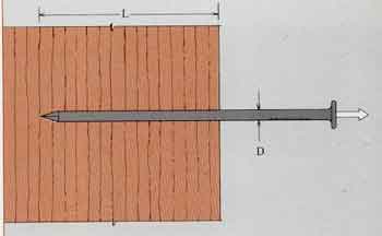 |
| 1ŚThe holding power of a nail is a function of its diameter (D), its driven length (L) and the grain direction and density of the wood into which it is driven. |
?icreasing the bearing against the fastener. Only when
?ippage occurs does the nail finally pull out.
Experiments have shown that in many woods, a spear ?oint with a slim taper
results in the greatest holding ?ower. However, the wood fibers also separate,
and in ?ome species this type of point causes splitting. A blunt ?oint has less
tendency to cause splitting, because a ?lug of compressed wood structure is torn
loose and ?ushed ahead of the point, rather than being pushed ?side to start a
split. However, the greater cell damage ?educes holding power. The common
diamond point, ?hen, is a compromise that seems to afford the greatest ?olding
power with the least splitting in common softwood structural lumber.
The fact that nails can be driven without preboring ?ilot holes has
apparently led to the assumption that ?hey should be driven without preboring.
An unfortu-?;ate corollary seems to be that nails are therefore lim-?ted to use
where they can be driven without splitting ?he wood or bending over. In reality,
the best holding ?lower develops when nail holes are prebored. While ?nost
woodworkers accept the idea of installing wood-?crews in prebored holes to
prevent splitting and to ?naximize holding power, they seldom consider
prebor-?ng nail holes. Pilot holes ranging from 60% of nail ?hank diameter for
low-density woods to 85% of shank diameter for high-density woods give maximum
with-drawal resistance. In routine construction and carpen-?ry it is obvious
that preboring is not feasible. For cab-?netmaking and other woodworking,
however, nails in-?talled in prebored holes are extremely effective fasten-?rs
and deserve greaterIn consideration.
In nailing two pieces together, driving the nail through the first piece
builds up a compression zone that may cause splitting or other disruptions as
the nail ?merges and enters the second piece. The resulting rupture can keep the
pieces from maintaining close contact.
Appropriate preboring eliminates this problem.
The holding power of nails diminishes over time following installation. The
long-term holding power, especially where extreme moisture variation causes
dimensional change in the wood, can be reduced to as little as one-sixth the
loads indicated by the formula given.
Holding power can be improved considerably by surface modification of the
nail shanks (2). Resin-coated nails (called cement-coated nails) have about
double normal holding power but this advantage disappears over lime. Withdrawal
resistance can be substantially improved by placing annular grooves on the nail
shank (3). Annularly threaded nails are understandably harder to drive, but when
installed into side-grain prebored holes they provide positive resisting
surfaces for bent-over fibers. Spiral-threaded nails have improved holding power
that appears least reduced over time, perhaps because of the minimum damage to
the holes as the nails "screw" into place.
All nails have less holding power when driven into end grain than into side
grain. Test results indicate that the difference is smallest with high-density
woods, but with low-density woods end-grain holding power may be as little as
halt of side-grain holding power.
 |
| 3ŚWhen a nail is driven perpendicular to the grain, annular grooves provide added bearing surface for the bent wood fibers, which resist withdrawal of the nail. |
1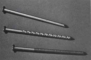 |
| 12ŚFrom top to bottom, a common nail with smooth, bright finish, a spiral-grooved nail and an annularly grooved nail. |
Unfortunately, one hears the flat statement that nailing into end grain
should be avoided on the grounds that holding power is reduced. Actually, the
lower holding power can be compensated for by preboring and increasing the
diameter, length or number of nails. Nailing into end grain, in fact, may be
beneficial in certain situations. For example, when a nail is driven into side
grain, later shrinkage shifts the wood along the nail shank, causing the nail
head to protrude rather than pushing the point deeper into the wood. The longer
the nail, the greater the protrusion. This is why, in dry-wall work, the
shortest nail that will hold the gypsum board in place is recommended. When the
wood swells, it moves equally away from each side of the shank center, thereby
backing the point still farther from the bottom of the hole. Repeated cycles
cause further emergence of the nail. In end grain, however, since wood does not
change dimension along its grain direction? using longer nails for greater
holding power does not increase nail popping.
In lateral loading (1), joint slip rather than maximum load is critical.
Stouter nails offer increased bearing against the wood so lateral load
resistance increases exponentially with nail diameter. (If the diameter is
doubled, the lateral resistance is increased by a factor of 2 3/2 -2 3 = 2.8It
is also important that the fastener be stout enough to transmit load without
bending. A long, slender nail crushes the wood near the surface and bends, and
then becomes loaded in withdrawal and "snakes" out of the hole.
The head design of a nail is also critical. The broad heads of common nails
are usually large enough to carry full withdrawal load without pulling through
the top member. However, the small heads of Finishing nails limit the
effectiveness of deep penetration since they readily pull through the top board.
Thus, while a joint can be made stronger by using longer common nails, beyond a
critical point a joint with finishing nails might best be improved by increasing
the diameter or the number of nails, if space permits.
Appearance is a strong influence in the bias against using nails in
woodworking joints. However, there are many places where nails could be the most
efficient and effective fastener, for example, half-blind dovetail joints
commonly used for drawer sides. It would be interesting to compare a well-nailed
half-blind tongue-and-rabbet joint for overall strength. Dare I even suggest
nailing a dovetail joint together?
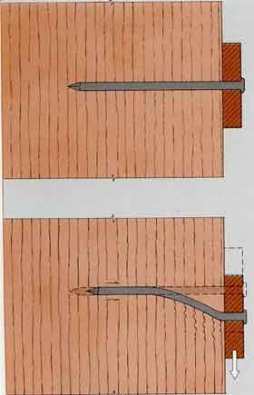 |
| 1ŚWhen a nail subject to laleral loading tails, it typically crushes the wood near the surface, then bends and pulls out of the hole. |
Woodscrews
Most woodworkers recognize the superiority of correctly installed woodscrews
(2) over other fasteners. Their great holding power is understandable in terms
of the positive engagement of the threads into relatively undamaged wood
structure. The key to maximum holding power is preboring pilol holes tor the
threaded portions of the screw and for the shank. Slightly undersized shank
holes should be prebored to provide a snug fit and firm bearing without
developing enough stress to cause splitting. Pilot holes for the threaded
portion should be from 70% of root diameter in low-density woods to 90% in
high-density woods. (In the densest woods, it may be best to bore the pilot hole
the same diameter as the root, especially for brass screws.) Lubricating the
threads with wax facilitates driving and minimizes screw breakage without loss
of holding power.
When woodscrews are correctly installed into the side grain of seasoned
wood, maximum withdrawal loads can he estimated by the empirical formula:
p= 15,700 G2DL,
p= maximum withdrawal load, in pounds
G = the specific gravity of the wood (Table 3, p. 8)
D = the screw shank diameter, in inches
L=the depth of penetration, in inches, of the
threaded portion of the screw into the member
receiving the point.
As with nails, the holding power of screws increases directly with diameter
and length, and exponentially with the density of the wood. Similarly, holding
power
loading conditions of long duration might be as little as 20% of the values
estimated by the formula given above. Screws driven into end-grain surfaces
average oniy about 75% as much holding power as those driven into side grain,
and holding power will be more erratic. As with nails, it is preferable to
design joints to load screws laterally rather than in direct withdrawal.
Besides nails and screws, a host of various other fasteners are available
for use with wood, such as clamp nails, corrugated fasteners and staples. In
addition, various hardware items serve as fasteners in the role of a "third
party," which is fastened to the two or more wood components by nails and
screws. These include mending plates, flat corner irons, angle braces, T-plates
and hinges. In evaluating the use and effecctiveness of each, the integrity
usually depends on the holding power of the attachment fasteners in terms of
stress application relative to grain direction. In construction joints,
for example, special framing anchors have been developed which transfer
loads from one member to the other by loading fasteners laterally rather than in
withdrawal. These anchor plates also provide for the proper number and placement
of fasteners (usually nails) for maximum strength.
 |
|
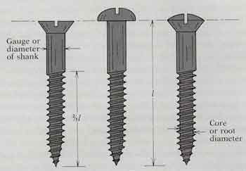
| 2ŚCommon woodscrews (from left to right): flathead, round-head, ovalhead. |
Adhesive joints
Laminated items assembled with glue have been discovered in the tombs of
eariy Egyptian pharaohs, and it is probable that the use of adhesive substances
for holding wood parts together predates recorded history. Through the ages,
most glues were made from fish, animals and vegetable starch and showed little
change or improvement. In this century, however, development of the plywood
industry initiated drastic changes in the types and properties of adhesives.
Further stimulated fay the demands of World War II and the scientific plunge
into the space age, a dynamic adhesive technology has given us numerous
multipurpose and specialized adhesives, with the promise of a continued parade
of new ones well into the future.
Today's woodworkers use adhesives in a number of waysŚto make large pieces
out of smaller ones (such as carving blocks and laminated beams), to create
combinations for strength or aesthetic improvement (such as plywood, veneers and
marquetry) and to join parts to create a final product, as in furniture,
sporting goods and structures. A complete discussion of gluing technology is
impossible here. However, certain basic considerations that may be overlooked or
misunderstood often cause serious gluing problems and are worth a systematic
review.
 |
1ŚThe five phases of a glue joint. |
Dull knives that pound, heat and glaze the surfaces can render the wood
physically and chemically unsuited for proper adhesion even though it is
smooth and flat. Planing saws are capable of producing surfaces acceptable
for gluing, but in general sawn surfaces are not as good as planed or
jointed ones.
Surface cleanliness must not be overlooked. Oil, grease, dirt, dust and even
polluted air can contaminate a wood surface and prevent proper adhesion.
Industry production standards usually call for "same-day" machining and
gluing. Freshly machining surfaces just before gluing is especially
important for species high in resinous or oily extractives. Where this is
not possible, washing surfaces with acetone is sometimes recommended. One
should not expect a board machined months or years ago to have surfaces of
suitable chemical purity. If lumber is flat and smooth but obviously dirty,
a careful light sanding with 240-grit or finer abrasive backed with a flat
block, followed by thorough dusting, can restore a chemically reactive
surface without seriously changing flatness. Coarse sanding, sometimes
thought to be helpful by "roughening" the surface, is actually harmful
because it leaves loose bits. Tests have shown that intentionally roughening
a surface, as in "toothed planing," does not improve adhesive-bond quality.
In summary, wood should be surfaced immediately prior to gluing, for
cleanliness and to minimize warp, and should be kept free of contamination
to ensure an acceptable gluing surface.
Shelf life is the period of time an adhesive remains usable after
distribution by the manufacturer. Unlike photographic films, adhesives are
not expiration-dated. Beware the container that has been on the dealer's
shelf too long. Outdated package styles are an obvious tip-off. It is wise
to mark a bottle or can with your date of purchase. It is amazing how fast
time can pass while glue sits idle in your workshop. If possible,
refrigerate glues in tight containers to prolong shelf life. In general, if
the glue is spreadablc when mixed according to instructions, it is suitable
for use. Adding water to restore spreadability is not a good practice.
The adage "when all else fails, read the instructions," all too often
applies to glue. It is unfortunate that instructions arc so incomplete on
retail glue containers. Manufacturers usually have fairly elaborate
technical specification sheets but supply them only to quantity consumers-
Too often many critical factors are left to the user's guesswork or
judgment. Mixing proportions and sequence usually are given clearly;
obviously they should be followed carefully.
Glues with a pH above 7 (alkaline), notably caseins, will absorb iron from a
container and react with certain woods such as oak, walnut, cherry and
mahogany to form a dark stain. Coffee cans or other ferrous con-metallic
mixing containers such as plastic cups or the bottoms of clean plastic
bleach jugs work nicely.
Once glue is mixed, the pot life, or working life, must be considered. Most
adhesives have ample working life to handle routine jobs. The period between
the beginning of spreading the glue and placing the surfaces together is
called open assembly time; closed assembly time indicates the interval
between joint closure and the development of full clamping pressure.
Allowable closed assembly lime is usually two or three times open assembly
time. With many ready-to-use adhesives, there is no minimum open assembly
time; spreading and closure as soon as possible is recommended, especially
in single spreading, to ensure transfer and wetting of the other surface. If
the joint is open too long, the glue may precure before adequate pressure is
applied. The result is called a dried joint, f n general, assembly time must
be shorter if the wood is porous, the mixture viscous, the wood at a low
moisture content, or the temperature above normal. (As a rule, it is a good
policy to avoid gluing where temperature of the room or of the wood is below
70 ░F.) With some adhesives, such as resorcinol, a minimum assembly time and
double spreading (that is, applying adhesive to each of the mating surfaces)
may be specified for dense woods and surfaces of low porosity, to allow
welting of the wood and to permit thickening of the adhesive to prevent
excessive squeeze-out. Proper spread is difficult to control. Too little
glue results in a starved joint and a poor bond. A little overage can be
tolerated, but too much results in wasteful and messy squeeze-out. Though
some squeeze-out is assurance that sufficient adhesive has been applied,
squeeze-out may cause problems in machining or finishing. With experience
the spread can be eyeballed. It is useful to obtain some commercial
specifications and conduct an
experiment to see just what they mean. Spreads are usually given in terras
of pounds of glue per thousand square feet of single glueline, or MSGL. A
cabinetmaker
will find it more convenient to convert to grams per square foot, by
dividing Ib./MSGL by 2,2. Thus a recommended spread of 50 Ib./MSGL, typical
of a resorcinol glue, is about 23 grams per square foot. Spread it evenly
onto a square foot of veneer for a fair visual estimate of the minimum that
should be used. Usually, the recommended spread appears rather meager.
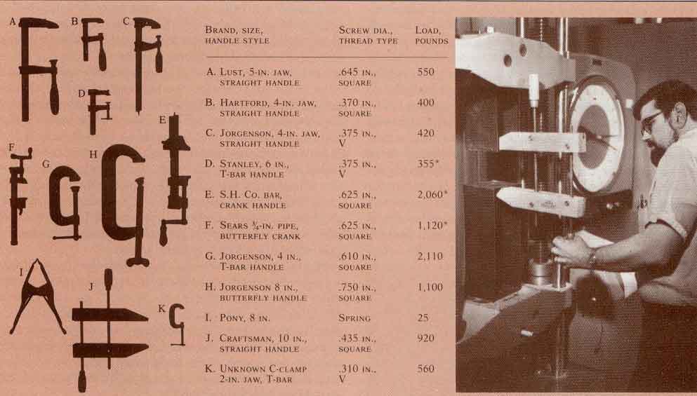 |
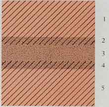
| Table 15ŚAverage clamping pressure of typical woodworking clamps. To find out just how mach load typical clamps could apply, Hoadley attached open steel frames to the crossheads of a universal timber-testing machine. With a clamp positioned to draw the frames together, the load applied was indicated directly. The clamps are described in the table, with the last column giving the average of three trials by average-sized Hoadley. tightening as if he were trying to gel maximum pressure in a gluing job. The quick-set clamp listed first in the lable was used to calibrale the setup: A secretary squeezed 330 Ib., a hockey player squeezed 640 lb., and Hoadley squeezed 550 Ib- Repealed trials by each person yielded readings that agreed to within 10%. An asterisk indicates that the clamp began lo bend, and the test was stopped at the value listed. |
Double spreading is recommended where feasible. This ensures full wetting of both surfaces, without relying on pressure and flatness to transfer the glue and wet
 |
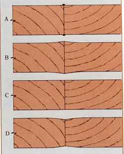 |
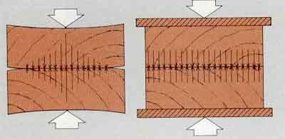
| 1ŚCover boards (cauls) distribule clamping pressure evenly | 2 Ś When an edge-glued panel (A) is .surfaced while the glue-line is still swollen with moisture (┬, č), a sunken joint (D) is the result. |